Open Shortest Path First - Routing Protocol
1. Context
I’m starting my network engineering internship with Union Pacific soon in a week, and my managers have been asking me to review networking concepts that the company frequently uses.
One of the important ones is OSPF as, I think, it is our main link state routing protocol within the company.
Therefore, I’m writing this blog post to document my learning process with this protocol.
I will attempt to explain what OSPF is, how it works, and what a network using OSPF is like in Packet Tracer.
2. What is OSPF and how it works
As stated earlier, OSPF stands for Open Shortest Path First, and it is a link-state routing protocol, which means it works on the second layer of the OSI model.
In general, the goal of routing protocols are to learn the best routes to transmit packets.
OSPF achieves this by learning about all routers and subnets in the entire network, and all routers within a network that uses OSPF contains the same information about the network.
To learn about other routers, they send out LSA(Link State Advertisement) that contains about their own router and subnets. After all the LSAs are flooded into the network, routers store these informations in LSDB(Link State Database).
The routers themselves must establish neighbor relationships before exchanging routes. Since this is a layer 2 protocol, routers does not exchange routing table(because routing table is for layer 3). Instead, they exchange what they know about the network topology.
After obtaining that information, they run the SFP algorithm to calculate the best route to put into their table.
How it works:
- Init state: when a router receives a Hello message from another router
- 2-way state: when the router replies with its own Hello message
- Exstart state: the neighbor routers exchange their LSDB and other link-state information
- Exchange state: DBD(Database Descriptor) packets are exchanged.
- Loading state: After checking, one neighbor will sends LSRs(Link State Requests) requesting for information about networks it does not know about. The other will reply with LSUs(Link State Updates) containing those information. After that, the roles are swapped.
- Full state: stable state where both routers have the same database and become neighbors.
3. OSPF Network
When a network uses OSPF, it is divided into areas.
An area in this context just means a logical grouping of networks and routers. All routers in the same area has the same topology table.
Routers in different areas do not know about each other.
The main benefit of having this is that the size of the network topology and the routing table’s size is greatly reduced, which then reduces the time it takes to run the routing protocol.
Area Border Routers(ABR) sit in between 2 areas and have 2 different interfaces. These routers serve the purpose of connecting devices from different area with each other.
4. OSPF in Packet Tracer
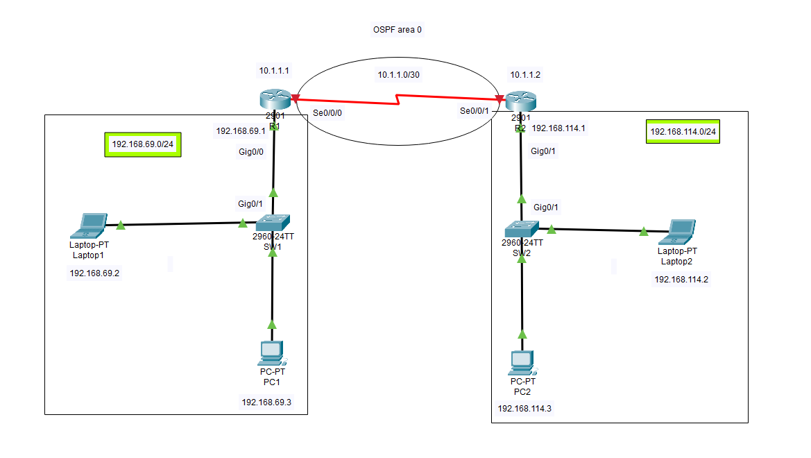
I. Set up the network
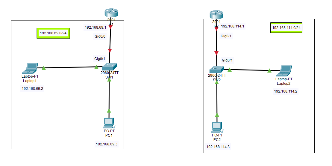
We will have 2 subnets which is 192.168.69.0/24 and 192.168.114.0/24.
In each subnet, there will be a laptop and a PC with the specified IP addresses connecting to each other with a switch. The gateway router will be at the gateway address.
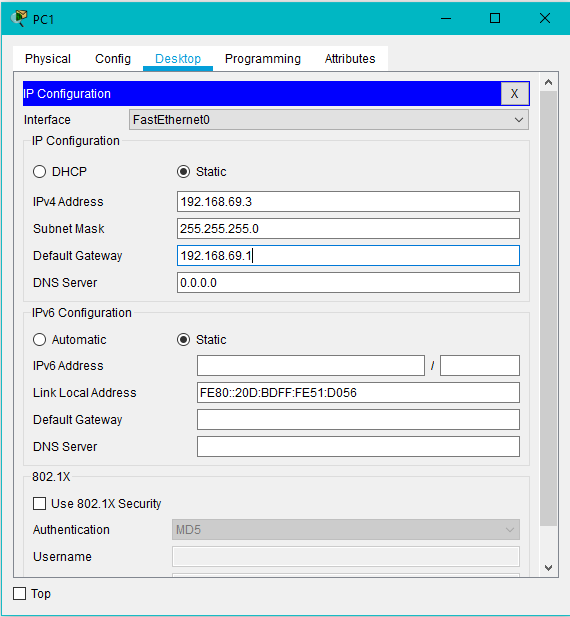
Next, we need to configure the Laptop and PC to have these IP addresses.
We can simply click on them, go to the Desktop tap, and click into the IP Configuration app.
From here, we can fill the IPv4 address and the default gateway of each end device.
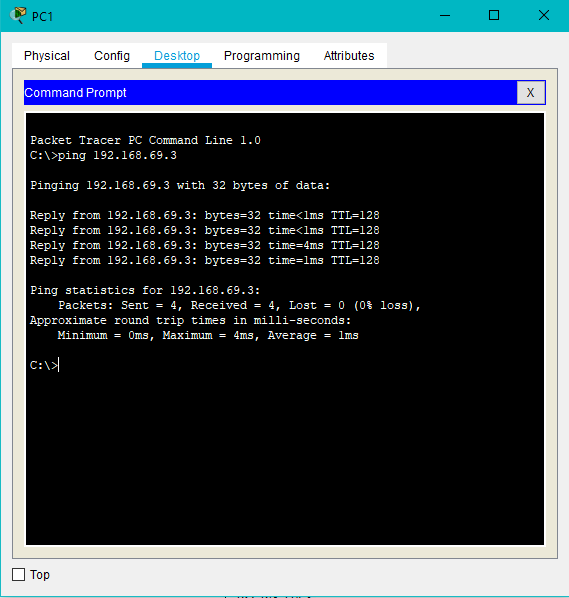
If we configure the IP addresses correctly, we can ping 2 end devices with each other in the same network through the switch.
Next, we need to configure the router of each network. We should run these commands in the router’s CLI.
en
conf t
hostname R1
interface gigabitEthernet 0/0
ip address 192.168.69.1 255.255.255.0
no shutdown
First, we turn enable mode on(priviledged mode) using the command en
Next, we log into configuration mode with conf t
Next, we enter gigabitEthernet0/0 interface with the command interface
Next, we change the IPv4 address of the router with the command ip!
Once we are done, all the lights in the network will be green, which means all the end devices can connect to their gateway router.
II. Connect routers as OSPF neighbors
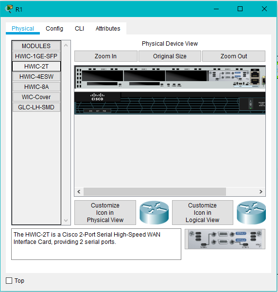
Since we need to connect the two routers with the Serial DCE cable, they should have a network card that support Serial cables.
In this case, I will use HWIC-2T since it gives 2 serial ports for both routers.
Next, we connect them using the Serial DCE cable. The network should now look like this.
Now, we need to configure the Serial interface of each router and assign them their IP address.
en
conf t
interface serial 0/0/0
ip address 10.1.1.1 255.255.255.252
So now, we have all the local end devices connect to the GigabitEthernet interface of their gateway router, and the routers’ serial interface are connected to each other in AREA 0. However, if we try to ping a device from a different network, we will see this.
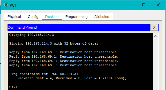
This means that OSPF is not working, the two subnets are not connected, and the routers are not OSPF neighbors.
We need to configure the OSPF protocol for each router.
en
conf t
router ospf 10
network 10.1.1.0 0.0.0.3 area 0
network 192.168.69.0 0.0.0.255 area 0
end
This will link both interfaces into the OSPF area 0. Once this is done, we can check if OSPF is on or not.
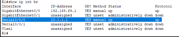
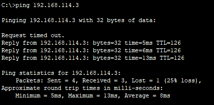
Now, if we try to ping a device in the other subnet, we will see that it succeeds!
5. Wrapping up
This is just a simple documentation of what OSPF is and how to configure it in Packet Tracer!
I hope you have learned a thing or two about this routing protocol as well as how it looks in a network!